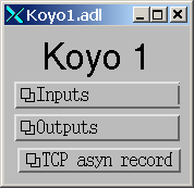
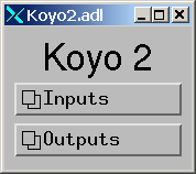
Koyo1.adl
Top level medm screen for the Koyo1 example application.
The modbus package is based on the modtcp and plctcp packages written by Rolf Keitel from Triumf. The modtcp package was originally converted to Linux by Ivan So from NSLS. modbus was extensively re-written for conversion to EPICS 3.14 and to use the EPICS asyn module. It now contains little of the original modtcp code, but retains much of the original architecture.
MODBUS is an application layer messaging protocol, positioned at level 7 of the OSI model, that provides client/server communication between devices connected on different types of buses or networks. It is typically used for communication with I/O systems, including Programmable Logic Controllers (PLCs).
Modbus supports the following 3 communication-link layers:
| Modbus Communication Links | |
|---|---|
| Link type | Description |
| TCP | TCP/IP using standard port 502. |
| RTU | RTU is normally run over serial communication links, i.e. RS-232, RS-422, or RS-485. RTU uses an additional CRC for packet checking. The protocol directly transmits each byte as 8 data bits, so uses "binary" rather than ASCII encoding. When using serial links start and end of message frames is detected by timing rather than by specific characters. RTU can also be run over TCP, though this is less common than the standard Modbus TCP without RTU. |
| Serial ASCII | Serial protocol, which is normally run over serial communication links, i.e. RS-232, RS-422, or RS-485. Serial ASCII uses an additional LRC for packet checking. The protocol encodes each byte as 2 ASCII characters. The start and end of message frames is detected by specific characters (":" to start a message and CR/LF to end a message). This protocol is less efficient than RTU, but may be more reliable in some environments. ASCII can also be run over TCP, though this is much less common than the standard Modbus TCP. |
This modbus package supports all of the above Modbus communication-link layers.
Modbus provides access to the following 4 types of data:
| Modbus Data Types | |||
|---|---|---|---|
| Primary tables | Object type | Access | Comments |
| Discrete Inputs | Single bit | Read-Only | This type of data can be provided by an I/O system. |
| Coils | Single bit | Read-Write | This type of data can be alterable by an application program. |
| Input Registers | 16-bit word | Read-Only | This type of data can be provided by an I/O system. |
| Holding Registers | 16-bit word | Read-Write | This type of data can be alterable by an application program. |
Modbus communication consists of a request message sent from the Modbus client to the Modbus server. The server replies with a response message. Modbus request messages contain:
modbus supports the following 9 Modbus function codes:
| Modbus Function Codes | ||
|---|---|---|
| Access | Function description | Function code |
| Bit access | Read Coils | 1 |
| Bit access | Read Discrete Inputs | 2 |
| Bit access | Write Single Coil | 5 |
| Bit access | Write Multiple Coils | 15 |
| 16-bit word access | Read Input Registers | 4 |
| 16-bit word access | Read Holding Registers | 3 |
| 16-bit word access | Write Single Register | 6 |
| 16-bit word access | Write Multiple Registers | 16 |
| 16-bit word access | Read/Write Multiple Registers | 23 |
Modbus addresses are specified by a 16-bit integer address. The location of inputs and outputs within the 16-bit address space is not defined by the Modbus protocol, it is vendor-specific. The following table lists some of the commonly used Modbus addresses for Koyo PLCs.
|
Modbus Addresses for Koyo DL05/06/240/250/260/430/440/450 PLCs |
||
|---|---|---|
| PLC Memory Type |
Modbus start address
Decimal (octal) |
Function codes |
| Discrete inputs and coils | ||
| Inputs (X) | 2048 (04000) | 2 |
| Special Relays (SP) | 3072 (06000) | 2 |
| Outputs (Y) | 2048 (04000) | 1, 5, 15 |
| Control Relays (C) | 3072 (06000) | 1, 5, 15 |
| Timer Contacts (T) | 6144 (014000) | 1, 5, 15 |
| Counter Contacts (CT) | 6400 (014400) | 1, 5, 15 |
| Stage Status Bits (S) | 6144 (012000) | 1, 5, 15 |
| Input registers and holding registers (V memory) | ||
| Timer Current Values (TA) | 0 (00) | 4 |
| Counter Current Values (CTA) | 512 (01000) | 4 |
| Global Inputs (VGX) | 16384 (040000) | 4 |
| Global Outputs (VGY) | 16512 (040200) | 3, 6, 16 |
| Inputs (VX) | 16640 (040400) | 4 |
| Outputs (VY) | 16704 (040500) | 3, 6, 16 |
| Control Relays (VC) | 16768 (040600) | 3, 6, 16 |
| Stage Status Bits (VS) | 16896 (041000) | 3, 6, 16 |
| Timer Contacts (VT) | 16960 (041100) | 3, 6, 16 |
| Counter Contacts (VCT) | 16992 (041140) | 3, 6, 16 |
| Special Relays (VSP) | 17024 (041200) | 4 |
Other PLC manufacturers will use different Modbus addresses.
Note that 16-bit Modbus addresses are commonly specified with an offset of 400001 (or 300001). This offset is not used by the modbus driver, it uses only the 16-bit address, not the offset.
Modbus read operations are limited to transferring 125 16-bit words or 2000 bits. Modbus write operations are limited to transferring 123 16-bit words or 1968 bits.
For more information about the Modbus protocol, the official Modbus specification can be found on the Web or in the modbus documentation directory.
The official specification for Modbus over TCP/IP can be found on the Web or in the modbus documentation directory.
The official specification for Modbus over serial can be found on the Web or in the modbus documentation directory.
CAUTION: modbus can provide access to all of the I/O and memory of the PLC. In fact, it is not even necessary to run a ladder logic program in the PLC at all. The PLC can be used as a "dumb" I/O subsystem, with all of the logic residing in the EPICS IOC. However, if a ladder logic program is being run in the PLC then the EPICS access with modbus must be designed carefully. For example, the EPICS IOC might be allowed to read any of the PLC I/O points (X inputs, Y outputs, etc.), but writes could be restricted to a small range of Control Registers, (e.g. C200-C240). The ladder logic would monitor these control registers, considering them to be "requests" from EPICS that should be acted upon only if it is safe to do so.
The architecture of the modbus module from the top-level down consists of the following 4 layers:
Because modbus makes extensive use of existing asyn facilities, and only needs to implement layers 2 and 3 above, the amount of code in modbus is quite small (fewer than 2,500 lines).
Each modbus port driver is assigned a single Modbus function code. Usually a drivers is also assigned a single contiguous range of Modbus memory, up to 2000 bits or 125 words. One typically creates several modbus port drivers for a single PLC, each driver reading or writing a different set of discrete inputs, coils, input registers or holding registers. For example, one might create one port driver to read discrete inputs X0-X37, a second to read control registers C0-C377, and a third to write control registers C300-C377. In this case the asyn address that is used by each record is relative to the starting address for that driver.
It is also possible to create a driver is allowed to address any location in the 16-bit Modbus address space. Each read or write operation is still limited to the 125/123 word limits. In this case the asyn address that is used by each record is the absolute Modbus address. This absolute addressing mode is enabled by passing -1 as the modbusStartAddress when creating the driver.
The restriction the modbus port driver to a single Modbus function does not apply to the doModbusIO() method. This method can be used for arbitrary Modbus IO using any function code. If absolute addressing is enabled as described above then the doModbusIO() function can also address any Modbus memory location.
The behavior of the port driver differs for read function codes (1, 2, 3, 4), write function codes (5, 6, 15, 16), and read/write function codes (23).
For read function codes (when absolute addressing is not being used) the driver spawns a poller thread. The poller thread reads the entire block of Modbus memory assigned to this port in a single Modbus transaction. The values are stored in a buffer in the driver. The delay between polls is set when the port driver is created, and can be changed later at run-time. The values are read by EPICS using the standard asyn interfaces (asynUInt32Digital, asynInt32, asynFloat64, etc.) The values that are read are the last stored values from the poller thread. The means that EPICS read operations are asynchronous, i.e. they can block. This is because although they do not directly result in Modbus I/O, they do need to wait for a mutex that indicates that the poller thread is done.
For read functions it is possible to set the EPICS records to "I/O Intr" scanning. If this is done then the port driver will call back device support whenever there is new data for that input. This improves efficiency, because such records only process when needed, they do not need to be periodically scanned.
The previous paragraphs describe the normal configuration for read operations, where relative Modbus addressing is being used. If absolute addressing is being used then the driver does not create a poller thread, because it does not know what parts of the Modbus address space should be polled. In this case read records cannot have SCAN=I/O Intr. They must either be periodically scanned, or scanned by directly causing the record to process, such as writing 1 to the .PROC field. Each time the record processes it will result in a separate Modbus read operation. NOTE: This is much less efficient than reading many registers at once with relative Modbus addressing. For this reason absolute Modbus addressing with read functions should normally be avoided.
For write function codes the driver does not itself create a separate thread. Rather the driver does the Modbus I/O immediately in response to the write operations on the standard asyn interfaces. This means that EPICS write operations are also asynchronous, i.e. they block because Modbus I/O is required. When the modbus driver is created it tells asynManager that it can block, and asynManager creates a separate thread that executes the write operations.
Word write operations using the asynUInt32Digital interface (with a mask parameter that is not 0x0 or 0xFFFF) are done using read/modify/write operations. This allows multiple Modbus clients to write and read single words in the same block of Modbus memory. However, it does not guarantee correct operation if multiple Modbus clients (or the PLC itself) can modify bits within a single word. This is because the Modbus server cannot perform the read/modify/write I/O as an atomic operation at the level of the Modbus client.
For write operations it is possible to specify that a single read operation should be done when the port driver is created. This is normally used so that EPICS obtains the current value of an output device when the IOC is initialized.
Modbus RTU specifies a minimum delay of 3.5 character times between writes to the device. The modbusInterposeConfig function allows one to specify a write delay in msec before each write.
Modbus function code 23 allows for writing a set of registers and reading a set of registers in a single operation. The read operation is performed after the write operation, and the register range to be read can be different from the register range to be written. Function code 23 is not widely used, and the write/read operation is not a good fit to the modbus driver model of read-only and write-only drivers. Function code 23 is implemented in modbus with the following restrictions:
modbus should run on all EPICS platforms. It has been tested on linux-x86, linux-x86_64, vxWorks, win32-x86, windows-x64, (native Windows with Microsoft Visual Studio 2010 C++ compiler), and cygwin-x86 (Windows with gcc compiler and Cygwin library).
The only thing that may be architecture dependent in modbus is the structure packing in modbus.h. The "#pragma pack(1)" directive used there is supported on gnu and Microsoft compilers. If this directive is not supported on some compilers of interest then modbus.h will need to have the appropriate architecture dependent code added.
Before modbus port drivers can be created, it is necessary to first create at least one asyn TCP/IP or serial port driver to communicate with the hardware. The commands required depend on the communications link being used.
For TCP/IP use the following standard asyn command:
drvAsynIPPortConfigure(portName, hostInfo, priority, noAutoConnect, noProcessEos)
Documentation on this command can be found in the asynDriver documentation.
The following example creates an asyn IP port driver called "Koyo1" on port 502 at IP address 164.54.160.158. The default priority is used and the noAutoConnect flag is set to 0 so that asynManager will do normal automatic connection management. The noProcessEos flag is set to 1 because Modbus over TCP does not require end-of-string processing.
drvAsynIPPortConfigure("Koyo1","164.54.160.158:502",0,0,1)
For serial RTU use the following standard asyn commands:
drvAsynSerialPortConfigure(portName, ttyName, priority, noAutoConnect, noProcessEos)
asynSetOption(portName, addr, key, value)
Documentation on these commands can be found in the asynDriver documentation.
The following example creates an asyn local serial port driver called "Koyo1" on /dev/ttyS1. The default priority is used and the noAutoConnect flag is set to 0 so that asynManager will do normal automatic connection management. The noProcessEos flag is set to 0 because Modbus over serial requires end-of-string processing. The serial port parameters are configured to 38400 baud, no parity, 8 data bits, 1 stop bit.
drvAsynSerialPortConfigure("Koyo1", "/dev/ttyS1", 0, 0, 0)
asynSetOption("Koyo1",0,"baud","38400")
asynSetOption("Koyo1",0,"parity","none")
asynSetOption("Koyo1",0,"bits","8")
asynSetOption("Koyo1",0,"stop","1")
For serial ASCII use the same commands described above for serial RTU. After the asynSetOption commands use the following standard asyn commands:
asynOctetSetOutputEos(portName, addr, eos)
asynOctetSetInputEos(portName, addr, eos)
Documentation on these commands can be found in the asynDriver documentation.
The following example creates an asyn local serial port driver called "Koyo1" on /dev/ttyS1. The default priority is used and the noAutoConnect flag is set to 0 so that asynManager will do normal automatic connection management. The noProcessEos flag is set to 0 because Modbus over serial requires end-of-string processing. The serial port parameters are configured to 38400 baud, no parity, 8 data bits, 1 stop bit. The input and output end-of-string is set to CR/LF.
drvAsynSerialPortConfigure("Koyo1", "/dev/ttyS1", 0, 0, 0)
asynSetOption("Koyo1",0,"baud","38400")
asynSetOption("Koyo1",0,"parity","none")
asynSetOption("Koyo1",0,"bits","8")
asynSetOption("Koyo1",0,"stop","1")
asynOctetSetOutputEos("Koyo1",0,"\r\n")
asynOctetSetInputEos("Koyo1",0,"\r\n")
After creating the asynIPPort or asynSerialPort driver, the next step is to add the asyn "interpose interface" driver. This driver takes the device-independent Modbus frames and adds or removes the communication-link specific information for the TCP, RTU, or ASCII link protocols. The interpose driver is created with the command:
modbusInterposeConfig(portName,
                      linkType,
                      timeoutMsec,
                      writeDelayMsec)
| modbusInterposeConfig command | ||
|---|---|---|
| Parameter | Data type | Description |
| portName | string | Name of the asynIPPort or asynSerialPort previously created. |
| linkType | int |
Modbus link layer type: 0 = TCP/IP 1 = RTU 2 = ASCII |
| timeoutMsec | int | The timeout in milliseconds for write and read operations to the underlying asynOctet driver. This value is used in place of the timeout parameter specified in EPICS device support. If zero is specified then a default timeout of 2000 milliseconds is used. |
| writeDelayMsec | int | The delay in milliseconds before each write from EPICS to the device. This is typically only needed for Serial RTU devices. The Modicon Modbus Protocol Reference Guide says this must be at least 3.5 character times, e.g. about 3.5ms at 9600 baud, for Serial RTU. The default is 0. |
For the serial ASCII example above, after the asynOctetSetInputEos command, the following command would be used. This uses a timeout of 1 second, and a write delay of 0 ms.
modbusInterposeConfig("Koyo1",2,1000,0)
Once the asyn IP or serial port driver has been created, and the modbusInterpose driver has been configured, a modbus port driver is created with the following command:
drvModbusAsynConfigure(portName,
                       tcpPortName,
                       slaveAddress,
                       modbusFunction,
                       modbusStartAddress,
                       modbusLength,
                       dataType,
                       pollMsec,
                       plcType);
| drvModbusAsynConfigure command | ||
|---|---|---|
| Parameter | Data type | Description |
| portName | string | Name of the modbus port to be created. |
| tcpPortName | string | Name of the asyn IP or serial port previously created. |
| slaveAddress | int | The address of the Modbus slave. This must match the configuration of the Modbus slave (PLC) for RTU and ASCII. For TCP the slave address is used for the "unit identifier", the last field in the MBAP header. The "unit identifier" is ignored by most PLCs, but may be required by some. |
| modbusFunction | int | Modbus function code (1, 2, 3, 4, 5, 6, 15, 16, 123 (for 23 read-only), or 223 (for 23 write-only)). |
| modbusStartAddress | int | Start address for the Modbus data segment to be accessed. For relative addressing this must be in the range 0-65535 decimal, or 0-0177777 octal. For absolute addressing this must be set to -1. |
| modbusLength | int |
The length of the Modbus data segment to be accessed. This is specified in bits for Modbus functions 1, 2, 5 and 15. It is specified in 16-bit words for Modbus functions 3, 4, 6, 16, or 23. Length limit is 2000 for functions 1 and 2, 1968 for functions 5 and 15, 125 for functions 3 and 4, and 123 for functions 6, 16, and 23. For absolute addressing this must be set to the size of required by the largest single Modbus operation that may be used. This would be 1 if all Modbus reads and writes are for 16-bit registers, but it would be 4 if 64-bit floats (4 16-bit registers) are being used, and 100 (for example) if an Int32 waveform record with NELM=100 is being read or written. |
| modbusDataType | int | This sets the default data type for this port. This is the data type used if the drvUser field of a record is empty, or if it is MODBUS_DATA. The supported Modbus data types and correponding drvUser fields are described in the table below. |
| pollMsec | int |
Polling delay time in msec for the polling thread for read functions. For write functions, a non-zero value means that the Modbus data should be read once when the port driver is first created. |
| plcType | string |
Type of PLC (e.g. Koyo, Modicon, etc.).
This parameter is currently used to print information in asynReport. It is also used to treat Wago devices specially if the plcType string contains the substring "Wago". See the note below. |
Modbus function codes 3, 4, 6, and 16 are used to access 16-bit registers. The Modbus specification does not define how the data in these registers is to be interpreted, for example as signed or unsigned numbers, binary coded decimal (BCD) values, etc. In fact many manufacturers combine multiple 16-bit registers to encode 32-bit integers, 32-bit or 64-bit floats, etc. The following table lists the data types supported by modbus. The default data type for the port is defined with the modbusDataType parameter described above. The data type for particular record can override the default by specifying a different data type with the drvUser field in the link. The driver uses this information to convert the number between EPICS device support and Modbus. Data is transferred to and from EPICS device support as epicsUInt32, epicsInt32, and epicsFloat64 numbers. Note that the data type conversions described in this table only apply for records using the asynInt32 or asynFloat64 interfaces, they do not apply when using the asynUInt32Digital interface. The asynUInt32Digital interface always treats the registers as unsigned 16-bit integers.
| Supported Modbus data types | ||
|---|---|---|
| modbusDataType value | drvUser field | Description |
| 0 | UINT16 | Unsigned 16-bit binary integers |
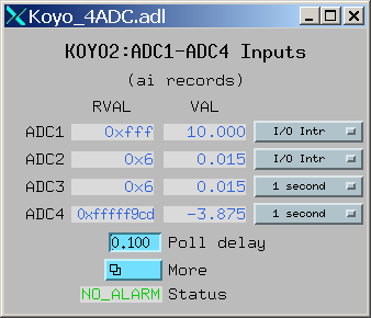
| 1 | INT16SM | 16-bit binary integers, sign and magnitude format. In this format bit 15 is the sign bit, and bits 0-14 are the absolute value of the magnitude of the number. This is one of the formats used, for example, by Koyo PLCs for numbers such as ADC conversions. |
| 2 | BCD_UNSIGNED | Binary coded decimal (BCD), unsigned. This data type is for a 16-bit number consisting of 4 4-bit nibbles, each of which encodes a decimal number from 0-9. A BCD number can thus store numbers from 0 to 9999. Many PLCs store some numbers in BCD format. |
| 3 | BCD_SIGNED | 4-digit binary coded decimal (BCD), signed. This data type is for a 16-bit number consisting of 3 4-bit nibbles, and one 3-bit nibble. Bit 15 is a sign bit. Signed BCD numbers can hold values from -7999 to +7999. This is one of the formats used by Koyo PLCs for numbers such as ADC conversions. |
| 4 | INT16 | 16-bit signed (2's complement) integers. This data type extends the sign bit when converting to epicsInt32. |
| 5 | INT32_LE | 32-bit integers, little endian (least significant word at Modbus address N, most significant word at Modbus address N+1) |
| 6 | INT32_BE | 32-bit integers, big endian (most significant word at Modbus address N, least significant word at Modbus address N+1) |
| 7 | FLOAT32_LE | 32-bit floating point, little endian (least significant word at Modbus address N, most significant word at Modbus address N+1) |
| 8 | FLOAT32_BE | 32-bit floating point, big endian (most significant word at Modbus address N, least significant word at Modbus address N+1) |
| 9 | FLOAT64_LE | 64-bit floating point, little endian (least significant word at Modbus address N, most significant word at Modbus address N+3) |
| 10 | FLOAT64_BE | 64-bit floating point, big endian (most significant word at Modbus address N, least significant word at Modbus address N+3) |
| 11 | STRING_HIGH | String data. One character is stored in the high byte of each register. |
| 12 | STRING_LOW | String data. One character is stored in the low byte of each register. |
| 11 | STRING_HIGH_LOW | String data. Two characters are stored in each register, the first in the high byte and the second in the low byte. |
| 11 | STRING_LOW_HIGH | String data. Two characters are stored in each register, the first in the low byte and the second in the high byte. |
Note that if it is desired to transmit BCD numbers untranslated to EPICS over the asynInt32 interface, then data type 0 should be used, because no translation is done in this case.
The following is an example ai record using 32-bit floating point values:
# ai record template for register inputs
record(ai, "$(P)$(R)") {
    field(DTYP,"asynFloat64")
    field(INP,"@asyn($(PORT) $(OFFSET))FLOAT32_LE")
    field(HOPR,"$(HOPR)")
    field(LOPR,"$(LOPR)")
    field(PREC,"$(PREC)")
    field(SCAN,"$(SCAN)")
}
This initial read operation is normally done at the same Modbus address as the write operations. However, Wago devices are different from other Modbus devices because the address to read back a register is not the same as the address to write the register. For Wago devices the address used to read back the initial value for a Modbus write function must be 0x200 greater than the address for the write function. This is handled by adding this 0x200 offset for the readback address if the plcType argument to drvModbusAsynConfigure contains the substring "Wago" (case sensitive). Note that this does not affect the address for Wago read functions. The user must specify the actual Modbus address for read functions.
Each drvAsynIPPort driver creates a separate TCP/IP socket connection to the PLC. It is possible to have all of the modbus port drivers share a single drvAsynIPPort driver. In this case all I/O to the PLC is done over a single socket in a "serial" fashion. A transaction for one modbus driver must complete before a transaction for another modbus driver can begin. It is also possible to create multiple drvAsynIPPort drivers (sockets) to a single PLC and, for example, use a different drvAsynIPPort for each modbus port. In this case I/O operations from multiple modbus drivers can proceed in parallel, rather than serially. This could improve performance at the expense of more CPU load on the IOC and PLC, and more network traffic.
It is important to note, however, that many PLCs will time out sockets after a few seconds of inactivity. This is not a problem with modbus drivers that use read function codes, because they are polling frequently. But modbus drivers that use write function codes may only do occasional I/O, and hence may time out if they are the only ones communicating through a drvAsynIPPort driver. Thus, it is usually necessary for modbus drivers with write function codes to use the same drvAsynIPPort driver (socket) as at least one modbus driver with a read function code to avoid timeouts.
The choice of how many drvAsynIPPort drivers to use per PLC will be based on empirical performance versus resource usage considerations. In general it is probably a good idea to start with one drvAsynIPPort server per PLC (e.g. shared by all modbus drivers for that PLC) and see if this results in satisfactory performance.
It can be convenient to specify the modbusStartAddress and modbusLength in octal, rather than decimal, because this is the convention on most PLCs. In the iocsh and vxWorks shells this is done by using a leading 0 on the number, i.e. 040400 is an octal number.
modbus implements the following standard asyn interfaces:
Because it implements these standard interfaces, EPICS device support is done entirely with the generic EPICS device support provided with asyn itself. There is no special device support provided as part of modbus.
It is necessary to use asyn R4-8 or later, because some minor enhancements were made to asyn to support the features required by modbus.
The following tables document the asyn interfaces used by the EPICS device support.
The drvUser parameter is used by the driver to determine what command is being sent from device support. The default is MODBUS_DATA, which is thus optional in the link specification in device support. If no drvUser field is specified, or if MODBUS_DATA is specified, then the Modbus data type for records using the asynInt32 and asynFloat64 interfaces is the default data type specified in the drvModbusAsynConfigure command. Records can override the default Modbus data type by specifying datatype-specific drvUser field, e.g. BCD_SIGNED, INT16, FLOAT32_LE, etc.
The offset parameter is used to specify the location of the data for a record relative to the starting Modbus address for that driver. This offset is specified in bits for drivers using Modbus functions 1, 2, 5, and 15 that control discrete inputs or coils. For example, if the Modbus function is 2 and the Modbus starting address is 04000, then offset=2 refers to address 04002. For a Koyo PLC the X inputs are at this Modbus starting address for Modbus function 2, so offset=2 is input X2.
If absolute addressing is being used then the offset parameter is an absolute 16-bit Modbus address, and is not relative to the starting Modbus address, which is -1.
The offset is specified in words for drivers using Modbus functions 3, 4, 6 and 16 that address input registers or holding registers. For example, if the Modbus function is set to 6 and the Modbus address is 040600 then offset=2 refers to address 040602. For a Koyo PLC the C control relays are accessed as 16-bit words at this Modbus starting address for Modbus function 6. offset=2 will thus write to the third 16 bit-word, which is coils C40-C57.
For 32-bit or 64-bit data types (INT32_LE, INT32_BE, FLOAT32_LE, FLOAT32_BE) the offset specifies the location of the first 16-bit register, and the second register is at offset+1, etc.
For string data types (STRING_HIGH, STRING_LOW, STRING_HIGH_LOW, STRING_LOW_HIGH) the offset specifies the location of the first 16-bit register, and the second register is at offset+1, etc.
asynUInt32Digital device support is selected with
field(DTYP,"asynUInt32Digital")
field(INP,"@asynMask(portName,offset,mask,timeout)drvUser")
| asynUInt32Digital Device Support | |||||
|---|---|---|---|---|---|
| Modbus function | Offset type | Data type | drvUser | Records supported | Description |
| 1, 2 | Bit | Single bit | MODBUS_DATA | bi, mbbi, mbbiDirect, longin |
value = (Modbus data & mask) (normally mask=1) |
| 3, 4, 23 | 16-bit word | 16-bit word | MODBUS_DATA | bi, mbbi, mbbiDirect, longin |
value = (Modbus data & mask) (mask selects bits of interest) |
| 5 | Bit | Single bit | MODBUS_DATA | bo, mbbo, mbboDirect, longout |
Modbus write (value & mask) (normally mask=1) |
| 6 | 16-bit word | 16-bit word | MODBUS_DATA | bo, mbbo, mbboDirect, longout |
If mask==0 or mask==0xFFFF does Modbus write (value) Else does read/modify/write: Sets bits that are set in value and set in mask, Clears bits that are clear in value and set in mask |
| Any | NA | NA | ENABLE_HISTOGRAM | bi, mbbi, mbbiDirect, longin |
Returns 0/1 if I/O time histogramming is disabled/enabled in driver |
| Any | NA | NA | ENABLE_HISTOGRAM | bo, mbbo, mbboDirect, longout |
If value = 0/1 then disable/enable I/O time histogramming in driver |
asynInt32 device support is selected with
field(DTYP,"asynInt32")
field(INP,"@asyn(portName,offset,timeout)drvUser")
or
field(INP,"@asynMask(portName,offset,nbits,timeout)drvUser")
The asynMask syntax is used for analog I/O devices, in order to specify the number of bits in the device. This is required for Modbus because the driver only knows that it is returning a 16-bit register, but not the actual number of bits in the device, and hence cannot return meaningful data with asynInt32->getBounds().
nbits>0 for a unipolar device. For example, nbits=12 means unipolar 12-bit device, with a range of 0 to 4095. nbits<0 for a bipolar device. For example, nbits=-12 means bipolar 12-bit device, with a range of -2048 to 2047)
Note: when writing 32-bit or 64-bit values function code 16 should be used if the device supports it. The write will then be "atomic". If function code 6 is used then the data will be written in multiple messages, and there will be an short time period in which the device has incorrect data.
| asynInt32 Device Support | |||||
|---|---|---|---|---|---|
| Modbus function | Offset type | Data type | drvUser | Records supported | Description |
| 1, 2 | Bit | Single bit | MODBUS_DATA | ai, bi, mbbi, longin | value = (epicsUInt32)Modbus data |
| 3, 4, 23 | 16-bit words | 16, 32, or 64-bit word | MODBUS_DATA (or datatype-specific value) | ai, mbbi, longin | value = (epicsInt32)Modbus data |
| 5 | Bit | Single bit | MODBUS_DATA | ao, bo, mbbo, longout | Modbus write value |
| 6, 16, 23 | 16-bit words | 16, 32, or 64-bit word | MODBUS_DATA (or datatype-specific value) | ao, mbbo, longout | Modbus write value |
| Any | NA | NA | MODBUS_READ | ao, bo, longout | Writing to a Modbus input driver with this drvUser value will force the poller thread to run once immediately, regardless of the value of POLL_DELAY. |
| Any | NA | NA | READ_OK | ai, longin | Returns number of successful read operations on this asyn port |
| Any | NA | NA | WRITE_OK | ai, longin | Returns number of successful write operations on this asyn port |
| Any | NA | NA | IO_ERRORS | ai, longin | Returns number of I/O errors on this asyn port |
| Any | NA | NA | LAST_IO_TIME | ai, longin | Returns number of milliseconds for last I/O operation |
| Any | NA | NA | MAX_IO_TIME | ai, longin | Returns maximum number of milliseconds for I/O operations |
| Any | NA | NA | HISTOGRAM_BIN_TIME | ao, longout | Sets the time per bin in msec in the statistics histogram |
asynFloat64 device support is selected with
field(DTYP,"asynFloat64")
field(INP,"@asyn(portName,offset,timeout)drvUser")
Note: when writing 32-bit or 64-bit values function code 16 should be used if the device supports it. The write will then be "atomic". If function code 6 is used then the data will be written in multiple messages, and there will be an short time period in which the device has incorrect data.
| asynFloat64 Device Support | |||||
|---|---|---|---|---|---|
| Modbus function | Offset type | Data type | drvUser | Records supported | Description |
| 1, 2 | Bit | Single bit | MODBUS_DATA | ai | value = (epicsFloat64)Modbus data |
| 3, 4, 23 | 16-bit words | 16, 32, or 64-bit word | MODBUS_DATA (or datatype-specific value) | ai | value = (epicsFloat64)Modbus data |
| 5 | Bit | Single bit | MODBUS_DATA | ao | Modbus write (epicsUInt16)value |
| 6, 16, 23 | 16-bit word | 16-bit word | MODBUS_DATA (or datatype-specific value) | ao | Modbus write value |
| Any | NA | NA | POLL_DELAY | ai, ao | Read or write the delay time in seconds between polls for the read poller thread. If ≤0 then the poller thread does not run periodically, it only runs when it is woken up by an epicsEvent signal, which happens when the driver has an asynInt32 write with the MODBUS_READ drvUser string. |
asynInt32Array device support is selected with
field(DTYP,"asynInt32ArrayIn")
field(INP,"@asyn(portName,offset,timeout)drvUser")
or
field(DTYP,"asynInt32ArrayOut")
field(INP,"@asyn(portName,offset,timeout)drvUser")
asynInt32Array device support is used to read or write arrays of up to 2000 coil values or up to 125 16-bit registers. It is also used to read the histogram array of I/O times when histogramming is enabled.
| asynInt32Array Device Support | |||||
|---|---|---|---|---|---|
| Modbus function | Offset type | Data type | drvUser | Records supported | Description |
| 1, 2 | Bit | Array of bits | MODBUS_DATA | waveform (input) | value = (epicsInt32)Modbus data[] |
| 3, 4, 23 | 16-bit word | Array of 16, 32 or 64-bit words | MODBUS_DATA (or datatype-specific value) | waveform (input) | value = (epicsInt32)Modbus data[] |
| 15 | Bit | Array of bits | MODBUS_DATA | waveform (output) | Modbus write (epicsUInt16)value[] |
| 16, 23 | 16-bit word | Array of 16, 32, or 64-bit words | MODBUS_DATA (or datatype-specific value) | waveform (output) | Modbus write value[] |
| Any | 32-bit word | NA | READ_HISTOGRAM | waveform (input) | Returns a histogram array of the I/O times in milliseconds since histogramming was last enabled. |
| Any | 32-bit word | NA | HISTOGRAM_TIME_AXIS | waveform (input) | Returns the time axis of the histogram data. Each element is HISTOGRAM_BIN_TIME msec. |
asynOctet device support is selected with
field(DTYP,"asynOctetRead")
field(INP,"@asyn(portName,offset,timeout)drvUser")
or
field(DTYP,"asynOctetWrite")
field(INP,"@asyn(portName,offset,timeout)drvUser")
asynOctet device support is used to read or write strings of up to 250 characters.
Note: The 0 terminating byte at the end of the string in a waveform record or stringout record is not written to the Modbus device.
Note: On input number of characters read from the Modbus device will be the lesser
of:
- the number of characters in the record minus the terminating 0 byte (39 for stringin,
NELM-1 for waveform) or
- the number of characters contained in the registers defined modbusLength argument
to drvModbusAsynConfigure (modbusLength or modbusLength*2 depending on whether the
drvUser field specifies 1 or 2 characters per register.
The string will be truncated if any of the characters read from Modbus is a 0 byte, but there is no guarantee that the last character in the string is followed by a 0 byte in the Modbus registers. Generally either modbusLength or NELM in the waveform record should be used to define the correct length for the string.
| asynOctet Device Support | |||||
|---|---|---|---|---|---|
| Modbus function | Offset type | Data type | drvUser | Records supported | Description |
| 3, 4, 23 | 16-bit word | String of characters | STRING_HIGH, STRING_LOW, STRING_HIGH_LOW, or STRING_LOW_HIGH | waveform (input) or stringin | value = Modbus data[] |
| 16, 23 | 16-bit word | String of characters | STRING_HIGH, STRING_LOW, STRING_HIGH_LOW, or STRING_LOW_HIGH | waveform (output) or stringout | Modbus write value[] |
modbus provides example template files in the modbusApp/Db directory. These include:
| Template Files | ||
|---|---|---|
| Files | Description | Macro arguments |
| bi_bit.template | asynUInt32Digital support for bi record with discrete inputs or coils. Mask=1. | P, R, PORT, OFFSET, ZNAM, ONAM, ZSV, OSV, SCAN |
| bi_word.template | asynUInt32Digital support for bi record with register inputs. | P, R, PORT, OFFSET, MASK, ZNAM, ONAM, ZSV, OSV, SCAN |
| mbbiDirect.template | asynUInt32Digital support for mbbiDirect record with register inputs. | P, R, PORT, OFFSET, MASK, SCAN |
| longin.template | asynUInt32Digital support for longin record with register inputs. Mask=0xFFFF. | P, R, PORT, OFFSET, SCAN |
| longinInt32.template | asynInt32 support for longin record with register inputs. | P, R, PORT, OFFSET, SCAN, DATA_TYPE |
| intarray_in.template | asynInt32Array support for waveform record with discrete, coil, or register inputs. | P, R, PORT, OFFSET, NELM, SCAN |
| bo_bit.template | asynUInt32Digital support for bo record with coil outputs. Mask=1. | P, R, PORT, OFFSET, ZNAM, ONAM |
| bo_word.template | asynUInt32Digital support for bo record with register outputs. | P, R, PORT, OFFSET, MASK, ZNAM, ONAM |
| mbboDirect.template | asynUInt32Digital support for mbboDirect record with register outputs. | P, R, PORT, OFFSET, MASK |
| longout.template | asynUInt32Digital support for longout record with register outputs. Mask=0xFFFF. | P, R, PORT, OFFSET |
| longoutInt32.template | asynInt32 support for longout record with register outputs. | P, R, PORT, OFFSET, DATA_TYPE |
| intarray_out.template | asynInt32Array support for waveform record with discrete, coil, or register outputs. | P, R, PORT, OFFSET, NELM |
| ai.template | asynInt32 support for ai record with LINEAR conversion | P, R, PORT, OFFSET, BITS, EGUL, EGUF, PREC, SCAN |
| aiFloat64.template | asynFloat64 support for ai record | P, R, PORT, OFFSET, LOPR, HOPR, PREC, SCAN, DATA_TYPE |
| ai_average.template | asynInt32Average support for ai record with LINEAR conversion. This support gets callbacks each time the poll thread reads the analog input, and averages readings until the record is processed. | P, R, PORT, OFFSET, BITS, EGUL, EGUF, PREC, SCAN |
| ao.template | asynInt32 support for ao record with LINEAR conversion | P, R, PORT, OFFSET, BITS, EGUL, EGUF, PREC |
| aoFloat64.template | asynFloat64 support for ao record | P, R, PORT, OFFSET, LOPR, HOPR, PREC, DATA_TYPE |
| stringin.template | asynOctet support for stringin record | P, R, PORT, OFFSET, DATA_TYPE, SCAN |
| stringout.template | asynOctet support for stringout record | P, R, PORT, OFFSET, DATA_TYPE, INITIAL_READBACK |
| stringWaveformIn.template | asynOctet input support for waveform record | P, R, PORT, OFFSET, DATA_TYPE, NELM, SCAN |
| stringWaveformOut.template | asynOctet output support for waveform record | P, R, PORT, OFFSET, DATA_TYPE, NELM, INITIAL_READBACK |
| asynRecord.template | Support for asyn record. Useful for controlling trace printing, and for debugging. | P, R, PORT, ADDR, TMOD, IFACE |
| poll_delay.template | Support for ao record to control the delay time for the poller thread. | P, R, PORT |
| poll_trigger.template | Support for bo record to trigger running the poller thread. | P, R, PORT |
| statistics.template | Support for bo, longin and waveform records to read I/O statistics for the port. | P, R, PORT, SCAN |
The following table explains the macro parameters used in the preceeding table.
| Macro Parameters | |
|---|---|
| Macro | Description |
| P | Prefix for record name. Complete record name is $(P)$(R). |
| R | Record name. Complete record name is $(P)$(R). |
| PORT | Port name for modbus asyn port. |
| OFFSET | Offset for Modbus data relative to start address for this port. |
| MASK | Bit mask used to select data for this record. |
| ZNAM | String for 0 value for bi/bo records. |
| ONAM | String for 1 value for bi/bo records. |
| ZSV | 0 severity for bi/bo records. |
| OSV | 1 severity for bi/bo records. |
| BITS | Number of bits for analog I/O devices. >0=unipolar, <0=bipolar. |
| DATA_TYPE | drvUser field specifying the Modbus data type. If this field is blank or is MODBUS_DATA then the default datatype specified in the drvModbusAsynConfigure command is used. Other allowed values are listed in the table above (UINT16, INT16SM, BCD_SIGNED, etc.) |
| EGUL | Engineering value for lower limit of analog device. |
| EGUF | Engineering value for upper limit of analog device. |
| LOPR | Lower display limit of analog device. |
| HOPR | Upper display limit of analog device. |
| PREC | Number of digits of precision for ai/ao records. |
| NELM | Number of elements in waveform records. |
| ADDR | Address for asyn record, same as OFFSET above. |
| TMOD | Transfer mode for asyn record. |
| IFACE | asyn interface for asyn record. |
| SCAN | Scan rate for record (e.g. "1 second", "I/O Intr", etc.). |
| INITIAL_READBACK | Controls whether an initial readback from the device is done for the stringout or string waveform output records. |
modbus builds an example application called modbusApp. This application can be run to control any number of Modbus PLCs.
In the iocBoot/iocTest directory there are several startup scripts for EPICS IOCs. These are designed to test most of the features of the modbus driver on Koyo PLCs, such as the DL series from Automation Direct.
../../bin/linux-x86/modbusApp st.cmd
One can also load Koyo1.cmd or Koyo2.cmd separately as in:
../../bin/linux-x86/modbusApp Koyo1.cmd
st.cmd.vxWorks is a simple example startup script to be run on vxWorks IOCs. It
just loads Koyo1.cmd and Koyo2.cmd.The following is the beginning of Koyo1.cmd when it is configured for serial RTU with slave address 1 on /dev/ttyS1. It also shows how to configure TCP and serial ASCII connections. (Koyo PLCs do not support ASCII however).
# Koyo1.cmd

dbLoadDatabase("../../dbd/modbus.dbd")
modbus_registerRecordDeviceDriver(pdbbase)

# Use the following commands for TCP/IP
#drvAsynIPPortConfigure(const char *portName,
#                       const char *hostInfo,
#                       unsigned int priority,
#                       int noAutoConnect,
#                       int noProcessEos);
drvAsynIPPortConfigure("Koyo1","164.54.160.158:502",0,0,1)
#modbusInterposeConfig(const char *portName,
#                      modbusLinkType linkType,
#                      int timeoutMsec,
#                      int writeDelayMsec)
modbusInterposeConfig("Koyo1",0,5000,0)

# Use the following commands for serial RTU or ASCII
#drvAsynSerialPortConfigure(const char *portName,
#                           const char *ttyName,
#                           unsigned int priority,
#                           int noAutoConnect,
#                           int noProcessEos);
#drvAsynSerialPortConfigure("Koyo1", "/dev/ttyS1", 0, 0, 0)
#asynSetOption("Koyo1",0,"baud","38400")
#asynSetOption("Koyo1",0,"parity","none")
#asynSetOption("Koyo1",0,"bits","8")
#asynSetOption("Koyo1",0,"stop","1")

# Use the following command for serial RTU
# Note: non-zero write delay (last parameter) may be needed.
#modbusInterposeConfig("Koyo1",1,1000,0)

# Use the following commands for serial ASCII
#asynOctetSetOutputEos("Koyo1",0,"\r\n")
#asynOctetSetInputEos("Koyo1",0,"\r\n")
# Note: non-zero write delay (last parameter) may be needed.
#modbusInterposeConfig("Koyo1",2,1000,0)

# NOTE: We use octal numbers for the start address and length (leading zeros)
#       to be consistent with the PLC nomenclature.  This is optional, decimal
#       numbers (no leading zero) or hex numbers can also be used.
#       In these examples we are using slave address 0 (number after "Koyo1").

# The DL205 has bit access to the Xn inputs at Modbus offset 4000 (octal)
# Read 32 bits (X0-X37).  Function code=2.
drvModbusAsynConfigure("K1_Xn_Bit",      "Koyo1", 0, 2,  04000, 040,    0,  100, "Koyo")

# The DL205 has word access to the Xn inputs at Modbus offset 40400 (octal)
# Read 8 words (128 bits).  Function code=3.
drvModbusAsynConfigure("K1_Xn_Word",     "Koyo1", 0, 3, 040400, 010,    0,  100, "Koyo")

# The DL205 has bit access to the Yn outputs at Modbus offset 4000 (octal)
# Read 32 bits (Y0-Y37).  Function code=1.
drvModbusAsynConfigure("K1_Yn_In_Bit",   "Koyo1", 0, 1,  04000, 040,    0,  100, "Koyo")

# The DL205 has bit access to the Yn outputs at Modbus offset 4000 (octal)
# Write 32 bits (Y0-Y37).  Function code=5.
drvModbusAsynConfigure("K1_Yn_Out_Bit",  "Koyo1", 0, 5,  04000, 040,    0,  1, "Koyo")

# The DL205 has word access to the Yn outputs at Modbus offset 40500 (octal)
# Read 8 words (128 bits).  Function code=3.
drvModbusAsynConfigure("K1_Yn_In_Word",  "Koyo1", 0, 3, 040500, 010,    0,  100, "Koyo")

# Write 8 words (128 bits).  Function code=6.
drvModbusAsynConfigure("K1_Yn_Out_Word", "Koyo1", 0, 6, 040500, 010,    0,  100, "Koyo")

# The DL205 has bit access to the Cn bits at Modbus offset 6000 (octal)
# Access 256 bits (C0-C377) as inputs.  Function code=1.
drvModbusAsynConfigure("K1_Cn_In_Bit",   "Koyo1", 0, 1,  06000, 0400,   0,  100, "Koyo")

# Access the same 256 bits (C0-C377) as outputs.  Function code=5.
drvModbusAsynConfigure("K1_Cn_Out_Bit",  "Koyo1", 0, 5,  06000, 0400,   0,  1,  "Koyo")

# Access the same 256 bits (C0-C377) as array outputs.  Function code=15.
drvModbusAsynConfigure("K1_Cn_Out_Bit_Array",  "Koyo1", 0, 15,  06000, 0400,   0,   1, "Koyo")

# The DL205 has word access to the Cn bits at Modbus offset 40600 (octal)
# We use the first 16 words (C0-C377) as inputs (256 bits).  Function code=3.
drvModbusAsynConfigure("K1_Cn_In_Word",  "Koyo1", 0, 3, 040600, 020,    0,  100, "Koyo")

# We access the same 16 words (C0-C377) as outputs (256 bits). Function code=6.
drvModbusAsynConfigure("K1_Cn_Out_Word", "Koyo1", 0, 6, 040600, 020,    0,  1,  "Koyo")

# We access the same 16 words (C0-C377) as array outputs (256 bits). Function code=16.
drvModbusAsynConfigure("K1_Cn_Out_Word_Array", "Koyo1", 0, 16, 040600, 020,    0,   1, "Koyo")

# Enable ASYN_TRACEIO_HEX on octet server
asynSetTraceIOMask("Koyo1",0,4)
# Enable ASYN_TRACE_ERROR and ASYN_TRACEIO_DRIVER on octet server
#asynSetTraceMask("Koyo1",0,9)

# Enable ASYN_TRACEIO_HEX on modbus server
asynSetTraceIOMask("K1_Yn_In_Bit",0,4)
# Enable all debugging on modbus server
#asynSetTraceMask("K1_Yn_In_Bit",0,255)
# Dump up to 512 bytes in asynTrace
asynSetTraceIOTruncateSize("K1_Yn_In_Bit",0,512)

dbLoadTemplate("Koyo1.substitutions")

iocInit
Note that this example is designed for testing and demonstration purposes, not as a realistic example of how modbus would normally be used. For example, it loads 6 drivers to access the C control relays using function codes 1 (read coils), 3 (read holding registers), 5 (write single coil), 6 (write single holding register), 15 (write multiple coils), and 16 (write multiple holding registers). This allows for testing of all function codes and record types, including waveforms. In practice one would normally only load at most 2 drivers for the C control relays, for example function code 1 (read coils), and function code 5 (write single coil).
There are other example applications in the iocTest directory, sim*.cmd and sim*.substitutions. These examples are used for testing the different Modbus data types and other features. I have used them with the Modbus Slave program, which is an inexpensive Modbus slave emulator.
There is another test application called testClient.cpp which demonstrates how to instantiate a drvModbusAsyn object and use it to perform Modbus I/O to an external device. This example is a pure C++ application running without an IOC. The same code could be used in a driver in an IOC.
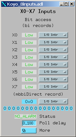
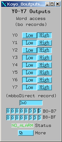
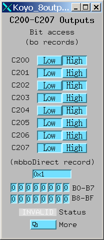
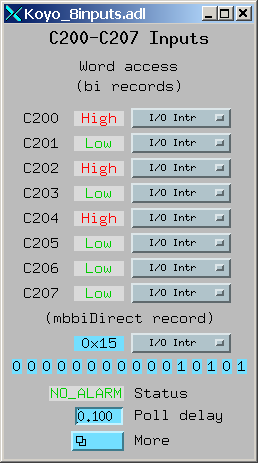
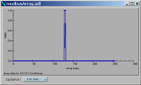
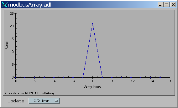
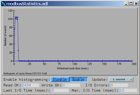
modbus provides example medm .adl files in the modtcpApp/op/adl directory. The following are screen shots of these screens from an IOC controlling a Koyo DL205 PLC.
One can obtain diagnostic output for a modbus port driver using the "dbior" or "asynPrint" commands at the iocsh or vxWorks shell. "asynReport" with no arguments will print a brief report for all asyn drivers, including the drvAsynIPPort or drvAsynSerialPort driver that modbus drivers are connected to, and for all modbus port drivers. For example, a partial output for the Koyo1 application when it is connected via TCP is:
epics> asynReport
Koyo1 multiDevice:No canBlock:Yes autoConnect:No
Port 164.54.160.158:502: Connected
K1_Xn_Bit multiDevice:Yes canBlock:No autoConnect:Yes
    addr 0 autoConnect Yes enabled Yes connected Yes exceptionActive No
    addr 1 autoConnect Yes enabled Yes connected Yes exceptionActive No
    addr 2 autoConnect Yes enabled Yes connected Yes exceptionActive No
    addr 3 autoConnect Yes enabled Yes connected Yes exceptionActive No
    addr 4 autoConnect Yes enabled Yes connected Yes exceptionActive No
    addr 5 autoConnect Yes enabled Yes connected Yes exceptionActive No
    addr 6 autoConnect Yes enabled Yes connected Yes exceptionActive No
    addr 7 autoConnect Yes enabled Yes connected Yes exceptionActive No
modbus port: K1_Xn_Bit
K1_Xn_Word multiDevice:Yes canBlock:No autoConnect:Yes
    addr 0 autoConnect Yes enabled Yes connected Yes exceptionActive No
To obtain more detailed information, one can request information for a specific modbus port driver, and output level >0 as follows:
epics> asynReport 5, "K1_Xn_Word"
K1_Xn_Word multiDevice:Yes canBlock:No autoConnect:Yes
    enabled:Yes connected:Yes numberConnects 1
    nDevices 1 nQueued 0 blocked:No
    asynManagerLock:No synchronousLock:No
    exceptionActive:No exceptionUsers 0 exceptionNotifys 0
    interfaceList
        asynCommon pinterface 0x4001d180 drvPvt 0x8094f78
        asynDrvUser pinterface 0x4001d10c drvPvt 0x8094f78
        asynUInt32Digital pinterface 0x4001d118 drvPvt 0x8094f78
        asynInt32 pinterface 0x4001d134 drvPvt 0x8094f78
        asynFloat64 pinterface 0x4001d148 drvPvt 0x8094f78
        asynInt32Array pinterface 0x4001d158 drvPvt 0x8094f78
    addr 0 autoConnect Yes enabled Yes connected Yes exceptionActive No
    exceptionActive No exceptionUsers 1 exceptionNotifys 0
    blocked No
modbus port: K1_Xn_Word
    asyn TCP server:    Koyo1
    modbusFunction:     3
    modbusStartAddress: 040400
    modbusLength:       010
    plcType:            Koyo
    I/O errors:         0
    Read OK:            5728
    Write OK:           0
    pollDelay:          0.100000
    Time for last I/O   3 msec
    Max. I/O time:      12 msec
To obtain run-time debugging output for a driver use the asynSetTraceMask and asynSetTraceIOMask commands. For example the following commands will show all I/O to and from the PLC from the underlying drvAsynIPPort driver:
epics> asynSetTraceIOMask "Koyo1",0,4   # Enable traceIOHex
epics> asynSetTraceMask "Koyo1",0,9     # Enable traceError and traceIODriver
epics>
2007/04/12 17:27:45.384 164.54.160.158:502 write 12

00 01 00 00 00 07 ff 02 08 00 00 20
2007/04/12 17:27:45.390 164.54.160.158:502 read 13

00 01 00 00 00 07 ff 02 04 00 00 00 00
2007/04/12 17:27:45.424 164.54.160.158:502 write 12

00 01 00 00 00 07 ff 03 41 00 00 08
2007/04/12 17:27:45.432 164.54.160.158:502 read 25

00 01 00 00 00 13 ff 03 10 00 00 00 00 00 00 00 00 00 00 00
00 00 00 00 00
...
epics> asynSetTraceMask "Koyo1",0,1    # Turn off traceIODriver
The following command shows the I/O from a specific modbus port driver:
epics> asynSetTraceIOMask "K1_Yn_In_Word",0,4   # Enable traceIOHex
epics> asynSetTraceMask "K1_Yn_In_Word",0,9     # Enable traceError and traceIODriver
epics>
2007/04/12 17:32:31.548 drvModbusAsyn::doModbusIO port K1_Yn_In_Word READ_REGISTERS
09 00 00 00 00 00 00 00
2007/04/12 17:32:31.656 drvModbusAsyn::doModbusIO port K1_Yn_In_Word READ_REGISTERS
09 00 00 00 00 00 00 00
2007/04/12 17:32:31.770 drvModbusAsyn::doModbusIO port K1_Yn_In_Word READ_REGISTERS
09 00 00 00 00 00 00 00
2007/04/12 17:32:31.878 drvModbusAsyn::doModbusIO port K1_Yn_In_Word READ_REGISTERS
09 00 00 00 00 00 00 00
2007/04/12 17:32:31.987 drvModbusAsyn::doModbusIO port K1_Yn_In_Word READ_REGISTERS
09 00 00 00 00 00 00 00
epics> asynSetTraceMask "K1_Yn_In_Word",0,1     # Disable traceIODriver
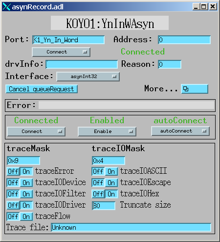
One can also load an EPICS asyn record on a modbus port, and then use EPICS channel access to turn debugging output on and off. The following medm screen shows how to turn on I/O tracing using this method.
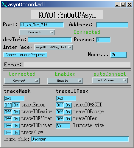
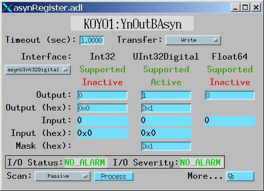
The asyn record can also be used to perform actual I/O to the PLC. For example the following screen shots shows the asyn record being used to control output Y1 on a PLC. Note that the ADDR field is set to 1 (to select Y1) and the data set to 1 (to turn on the output). Each time the asyn record is processed the value will be sent to the PLC.
The following are the main enhancements of modbus compared to the modtcp and plctcp packages from Triumf:
The following are some drawbacks of modbus compared to the modtcp and plctcp packages from Triumf: